


Three axis turntable: analysis of the principle of three degree of freedom motion simulation
Three axis inertia testing turntable: analysis of the principle of three degree of freedom motion simulation
In high-end equipment fields such as aerospace, inertial navigation, and robot control, the performance of inertial devices (gyroscopes, accelerometers, etc.) directly determines the attitude control accuracy and navigation reliability of the carrier. The three-axis inertial testing turntable, as the core testing equipment, has the core function of accurately reproducing the posture and angular motion of objects in three-dimensional space in the laboratory environment, providing controllable and repeatable motion excitation for the calibration, testing, and verification of inertial devices. Unlike single axis or double axis turntables, three-axis turntables achieve full space attitude simulation through three mutually orthogonal rotation axes. Their motion simulation principles integrate multidisciplinary technologies such as mechanical design, kinematics, and control engineering, making them an indispensable key link in the high-end equipment research and development chain.
This article will start from the core definition and systematically analyze the underlying logic, implementation path, and key technologies of the three degree of freedom motion simulation of the three-axis inertial testing turntable.
1、 Core concept: The essential relationship between three-axis inertial testing turntable and three degrees of freedom motion
To understand its motion simulation principle, it is necessary to first clarify the connotations of two core concepts: three-axis inertial testing turntable and three degree of freedom rotational motion.
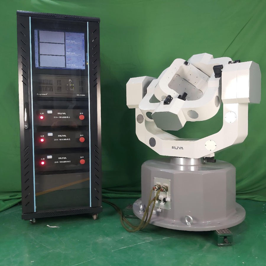
The three-axis inertial testing turntable is a high-precision electromechanical integrated device, which consists of a mechanical frame, a drive system, a measurement feedback system, and a control system. Its core design goal is to provide precise angular motion around three independent degrees of freedom for the tested inertial devices (such as the inertial measurement unit IMU) installed on the table through three orthogonal rotation axes, simulating the attitude changes of the carrier (aircraft, satellite, robot, etc.) in real scenarios, such as pitch, yaw, and roll of the aircraft, and orbit attitude adjustment of the satellite.
From a kinematic perspective, the attitude changes of any rigid body in space can be fully described by three independent rotational degrees of freedom, which correspond to three mutually orthogonal rotation axes that intersect at one point (turntable center point/test center), ensuring that the sensitive center of the tested device always coincides with the turntable center and avoiding the influence of additional displacement on test accuracy. These three degrees of freedom correspond to yaw motion around the vertical axis (azimuth angle), pitch motion around the horizontal axis (pitch angle), and roll motion around the axis parallel to the table (roll angle). The coordinated motion of the three can reproduce any spatial attitude, which is the theoretical basis of three-axis turntable motion simulation.
Unlike single axis turntables that can only simulate single direction rotation and dual axis turntables that cannot achieve full attitude coverage, three-axis turntables break the dimensional limitations of motion simulation through collaborative control of three degrees of freedom, and can realistically reproduce the dynamic attitude of the carrier under complex working conditions, meeting the requirements of high-precision inertial device full condition testing.
2、 Mechanical Fundamentals: Design Logic of Structural Carriers for Three Degree of Freedom Motion
The three degree of freedom motion simulation of the three-axis inertial testing turntable first relies on a precise mechanical frame structure, which consists of three orthogonal rotating frames (outer frame, middle frame, and inner frame), each corresponding to one degree of freedom. The motion is compounded and coordinated through hierarchical nesting. Typical frame structures include vertical (U-O-O type, T-U-T type, etc.) and horizontal. Among them, vertical structures are widely used in high-precision testing scenarios in the aerospace field due to their strong stability and outstanding load capacity. Their structural design follows the three principles of "orthogonality, concentricity, and rigidity".
2.1 Functional division of the three major frameworks (taking vertical structure as an example)
The hierarchical nested design of the three frameworks ensures the independence and synergy of each degree of freedom motion, with the specific division of labor as follows:
1. Outer frame (azimuth/yaw axis): As the foundation of the entire turntable, it is installed perpendicular to the horizontal plane, with its rotation axis in the vertical direction. It is responsible for driving the middle frame, inner frame, and tested device to rotate around the vertical axis together, simulating the yaw motion of the carrier in the horizontal plane (such as ship heading adjustment and aircraft horizontal turning). The outer frame needs to have high rigidity and stability, bear the weight and load of the entire turntable, and its rotation accuracy directly affects the accuracy of the overall posture simulation.
2. Mid frame (downward axis): nested inside the outer frame, its rotation axis is horizontal and orthogonal to the outer frame axis. It is responsible for driving the inner frame and the tested device to rotate around the horizontal axis, simulating the pitch motion of the carrier (such as aircraft head up and head down, satellite pitch attitude adjustment). The design of the middle frame needs to balance rigidity and lightweight, avoiding excessive weight that may increase the driving load of the outer frame. At the same time, it is necessary to ensure the orthogonal accuracy with the outer and inner frames, and reduce the attitude error caused by axis deviation.
3. Inner frame (rolling axis): nested inside the middle frame, its rotation axis is orthogonal to the middle frame axis and perpendicular to the tabletop, directly driving the tabletop and the tested device to rotate around the axis, simulating the rolling motion of the carrier (such as aircraft roll, robot attitude adjustment). The inner frame is the part directly connected to the device under test, and its rotational accuracy and dynamic response speed have the most direct impact on the test results. High precision bearings and lightweight materials are usually used to ensure smooth and accurate motion.
2.2 Key structural design requirements
To achieve high-precision three degree of freedom motion simulation, the mechanical structure needs to meet three core requirements: first, orthogonality. The three rotating axes must be strictly perpendicular to each other, and the perpendicularity error of the axis system is usually controlled at the level of arcseconds to avoid attitude calculation errors caused by axis deviation; The second is concentricity. The rotation centers of the three axes need to intersect at the same point (test center), with a deviation controlled within 0.5mm, to ensure that the sensitive center of the tested device is always at the center of motion and eliminate the influence of additional centrifugal force; The third is high rigidity and low vibration. The frame is made of high rigidity materials (such as aluminum alloy and alloy steel), combined with precision bearings and shock-absorbing structures, to reduce vibration during high-speed motion or long-term operation, and avoid vibration interference with the measurement accuracy of inertial devices.
3、 Principle Core: Mathematical Modeling and Attitude Solution of Three Degree of Freedom Motion
The simulation of the three degrees of freedom motion of a three-axis turntable essentially involves controlling the rotation angle, angular velocity, and angular acceleration of the three axes, coordinating their motion according to specific mathematical laws, and reproducing the spatial posture of the carrier. The core theoretical basis is the Euler angle principle and attitude matrix transformation, which establishes a corresponding relationship between spatial attitude and the rotation parameters of the three axes through mathematical modeling, achieving precise control and simulation of attitude.
3.1 Euler angles and three degree of freedom attitude description
The attitude of any rigid body in space can be fully described by three Euler angles (yaw angle ψ, pitch angle θ, roll angle φ), which correspond to the rotation angles of the three axes of the turntable. The rotation sequence (such as yaw pitch roll) determines the final state of the attitude. It should be noted that the Euler angle has a "universal joint lock" problem (when the pitch angle is ± 90 °, the yaw angle and roll angle will be coupled). Therefore, in practical applications, the quaternion method is usually used for attitude calculation to avoid attitude loss caused by universal joint lock and ensure the continuity and accuracy of full space attitude simulation.
Specifically, the target posture of the tested carrier can be represented by Euler angles or quaternions. The control system decomposes the target posture into three axis rotation commands, which respectively drive the outer frame, middle frame, and inner frame to rotate. Finally, through the coordinated motion of the three axes, the tested device is adjusted to the target posture. For example, when simulating the diving attitude of an aircraft, the middle frame (pitch axis) rotates clockwise (pitch angle decreases), while the inner frame (roll axis) is fine tuned according to attitude requirements, and the outer frame (yaw axis) remains fixed. The three work together to achieve accurate simulation of diving attitude.
3.2 Attitude Matrix and Motion Coupling Control
To achieve collaborative control of three degrees of freedom, it is necessary to establish a mapping relationship between the target attitude and the rotation parameters of each axis through the attitude matrix. The attitude matrix is a 3x3 orthogonal matrix consisting of three trigonometric functions with Euler angles, which can describe the rotational transformation process of a rigid body from the initial attitude to the target attitude. Through the inverse transformation of the attitude matrix, the target attitude can be decomposed into the rotation angles of three axes, providing precise control instructions for the driving system.
Due to the hierarchical nesting of the three frameworks, the rotation of one axis will cause changes in the spatial position of other axes, forming motion coupling (such as when the middle frame rotates, the direction of the rotation axis of the inner frame will change with the posture of the middle frame). Therefore, in the process of motion control, it is necessary to eliminate coupling effects through decoupling algorithms to ensure that the motion of each axis is independent and accurate. Common decoupling methods include feedforward decoupling, feedback decoupling, etc., which improve the accuracy and dynamic response speed of attitude simulation by compensating for coupling errors in real time.
4、 Implementation path: closed-loop driving and control of three degree of freedom motion
Mechanical structure is the carrier of motion simulation, mathematical modeling is the theoretical basis, and the collaborative work of drive system and control system is the core path to achieve precise motion simulation in three degrees of freedom. The three-axis turntable ensures the accuracy and stability of motion simulation through closed-loop control of "instruction input drive execution measurement feedback error correction". Its core components include the drive system, measurement feedback system, and control system.
4.1 Drive System: Power Source for Three Degree of Freedom Motion
The core function of the drive system is to provide precise driving torque for the three axes according to the instructions of the control system, achieving precise control of angle, angular velocity, and angular acceleration. At present, the mainstream driving methods are divided into electric drive and electro-hydraulic hybrid drive. DC torque motors are widely used in position and servo systems and are ideal execution components for high-precision servo systems. They have the characteristics of low speed, high torque, strong overload capacity, fast response, good linearity, and small torque fluctuations. They can directly drive loads without reducing transmission gears, thereby improving the operating accuracy of the system; Electro hydraulic hybrid drive is suitable for high load, high-power testing requirements, such as testing large aircraft inertial systems.
As the driving core, DC torque motors require high-precision speed control and position control capabilities, coupled with precision reducers (such as harmonic reducers), to convert the high-speed rotation of the motor into low-speed high-precision rotation of the frame, while providing sufficient driving torque to overcome frame inertia and load resistance. Each axis is equipped with an independent drive unit, ensuring that the three degrees of freedom of motion can be independently controlled and work together to achieve precise simulation of complex postures. Its angular velocity range can cover ± 0.001-400 °/s, meeting the requirements of full condition testing from static calibration to transient response.
4.2 Measurement feedback system: a key link in ensuring accuracy
The function of the measurement feedback system is to collect real-time parameters such as rotation angle, angular velocity, and angular acceleration of the three axes, and feed them back to the control system to form a closed-loop control, ensuring the accuracy of motion simulation. The core measuring devices include angle encoders, angular velocity sensors, etc. The accuracy of angle encoders (such as photoelectric encoders) directly determines the attitude control accuracy of the turntable. Currently, the angle positioning and repeatability accuracy of high-end three-axis turntables can reach ± 2 ", and the angular position resolution can reach ± 0.0001 °, which can meet the strict requirements of high-precision inertial device calibration.
The measurement feedback system needs to have high response speed and reliability, be able to capture the motion status of the three axes in real time, and quickly transmit measurement data to the control system. At the same time, it is necessary to use error compensation algorithms to correct the system errors of the measuring device itself (such as zero point error and scale error) and the errors caused by the mechanical structure (such as shaft deviation and vibration error), further improving the measurement accuracy and providing accurate feedback data for closed-loop control. The technical indicators of the turntable are calibrated using angle standard equipment to ensure the traceability of measurement data.
4.3 Control System: Three Degrees of Freedom Collaborative 'Brain'
The control system is the core of the three-axis turntable three degree of freedom motion simulation, responsible for receiving test instructions (such as target posture and motion trajectory), decomposing the target posture into control instructions for three axes through mathematical modeling and decoupling algorithms, driving the driving system to execute motion, and dynamically correcting control instructions based on real-time data from the measurement feedback system to eliminate errors and ensure the accuracy and stability of motion simulation.
The core functions of the control system include: firstly, attitude calculation, which converts the target attitude (Euler angle or quaternion) into three axis rotation parameters to avoid universal lock problems; The second is decoupling control, which eliminates the motion coupling between the three axes and ensures that the movements of each axis are independent and coordinated; The third is error correction, which adjusts the driving instructions in real-time based on measurement feedback data to compensate for system errors and external interference; The fourth is trajectory planning. Based on testing requirements, plan the motion trajectories of three axes (such as uniform rotation, variable speed rotation, sinusoidal oscillation, etc.) to simulate complex postures. Some measurement and control software also supports multiple control modes such as position mode, velocity mode, and oscillation mode to meet the needs of different testing scenarios.
At present, control systems mostly use PLC, DSP or industrial computers as the control core, combined with advanced control algorithms (such as PID control, fuzzy control, neural network control), to achieve high-precision and high dynamic response collaborative control. Among them, improved PID control (such as adaptive PID) can adapt to the nonlinear and time-varying characteristics of the system, effectively improving control accuracy; Fuzzy control and neural network control can handle uncertain factors in the system, enhance the system's anti-interference ability, and further optimize the stability of motion simulation.
5、 Key technical difficulties and precision assurance measures
The core difficulty of simulating the three degree of freedom motion of a three-axis inertial testing turntable lies in achieving collaborative control of "high precision, high stability, and high dynamic response". Its accuracy is affected by multiple factors such as mechanical structure, drive system, measurement system, and control system. To address these difficulties, targeted precision assurance measures need to be taken to ensure the accuracy and reliability of motion simulation and meet the stringent requirements of inertial device testing.
5.1 Core technical difficulties
1. Axis orthogonality and concentricity errors: The orthogonality and concentricity accuracy of the three axes directly affect the accuracy of attitude calculation. Even small deviations during mechanical processing and assembly can lead to attitude simulation errors, especially in terms of angular second level accuracy requirements, which place extremely high demands on processing and assembly processes;
2. Motion coupling interference: The hierarchical nesting of three frameworks leads to motion coupling, where the motion of one axis can interfere with the posture of other axes. Especially in high-speed dynamic motion scenarios, coupling interference can significantly affect control accuracy and requires complex decoupling algorithms to eliminate interference;
3. System errors and external interference: Dead zones in the drive system, zero drift in the measurement system, external vibrations, and other factors can all lead to motion simulation errors. Error compensation and anti-interference design are needed to improve the stability of the system;
4. Balance between dynamic response and precision: High dynamic response requires the driving system to respond quickly to control instructions, while high precision requires the system to run smoothly. There is a certain contradiction between the two, and it is necessary to optimize control algorithms and mechanical structures to achieve a balance between the two. For example, by using high rigidity structures and high-precision servo drives, dynamic response and smooth operation can be balanced.
5.2 Precision assurance measures
1. Precision machining and assembly: adopting high-precision machining technology to ensure the accuracy of the axis system of the three frames; By precision assembly and calibration, adjust the orthogonality and concentricity of the shaft system to reduce mechanical errors; Simultaneously using high rigidity materials and precision bearings to enhance structural stability, the flatness and end face runout of the console surface are within 0.02mm, and the load capacity is enhanced (up to 45Kg or more);
2. Advanced decoupling and control algorithms: using quaternion attitude calculation to avoid universal lock problems; Eliminating motion coupling interference through feedforward decoupling, feedback decoupling and other algorithms; Optimize control algorithms such as adaptive PID and fuzzy neural network control to improve the dynamic response speed and control accuracy of the system, achieving a balance between dynamic response and accuracy;
3. High precision measurement and error compensation: using high-precision angle encoders and angular velocity sensors to improve measurement accuracy; Establish an error model through calibration experiments to compensate for measurement errors and system errors in real-time; Adopting a shock-absorbing structure to reduce external vibration interference and ensure smooth system operation, some equipment can also provide complete and verifiable data reports covering all positions, velocities, and mechanical parameters, ensuring the reliability and traceability of test data.